
Figure 57: A stringer loaded with forces at both ends
Stringers are the elements of a stringer-panel model that carry only normal stresses. In case of tension, a stringer contains steel reinforcement bars. In case of compression it represents a strut in the structure which could be strengthened with compression reinforcement.
This Appendix consists of three major Sections. In the first Section the equations of a stringer without axial shear load are derived. This is in fact the elementary constitutive relation that is used in the second Section to derive the relations of a stringer with a shear load distributed over its length. In the last Section the ductility of the stringer is discussed. The sections are complemented with the unambiguous computer code for implementation of the derived relations.
Consider a reinforced concrete bar with forces at both ends as drawn in Figure 57. The objective of this Section is to derive the mechanical behaviour of this member. Fortunately, many experiments are performed on such simple members to investigate tension-stiffening, cracks and ductility which are used to support the derivation. 1

Figure 57: A stringer loaded with forces at both ends
If we assume that no bond slip occurs, the reinforcing steel and concrete elongate equally. So the average strain - defined as the elongation divided by the length - of steel and concrete are the same. When the stringer is not cracked the local strain is constant over the stringer length. In the steel the stress is ss = Ese and in the concrete the stress is sc = Ece. So, the resulting stringer force is
In the relations the following symbols are and will be used
Substitution of sc = Ec e and ss = Es e in the previous relation yields
With the definition of the stiffness ratio
this can be formulated as
The concrete cracks when the stress fcr = Ec ecr is reached. So, the force Ncr at which the first crack occurs is
Ncr = fcr Ac (1 + x)
Due to the cracking the stiffness of the stringer is reduced. Eurocode 2 gives the following empirical relation for the average strain e after cracking [ENV, art. 4.4.2.4 (4.81), p. 171]
![]()
In which are used
|
es Ncr N |
strain of steel in the crack force in the reinforcement when the first crack occurs at the position of the crack force in the reinforcement at a crack |
The relation is valid for both the crack formation phase and stabilised cracking. The term es Ncr2 / N 2 takes into account the tension-stiffening of the concrete on the reinforcement. The formula yields very good results in crack width calculations [Braam 1990, p. 21], however, when the concrete cracks (N = Ncr) the relation predicts no strain. This cannot be correct since then a small elastic strain is present. Therefore the expression is adapted to include the elastic strain
![]()
Because x is smaller than 1, the improved relation will give approximately the same result. As Figure 58 shows, now a continuous transition occurs between the elastic and the cracked stage.
The strain of the steel in a crack is
![]()
With this the average strain in the cracked stage can be expressed as
![]()

Figure 58: Tension-stiffening of the cracked stringer
As soon as the stress in the steel reaches the yield stress fy the stringer force N will hardly increase. Its value is now
Nyr = As fy
The stringer will continue to yield until its ductility is exhausted as described in Section 3. 2
For the uniaxal stress state in concrete the following parabolic relation is often used

In this the following symbols are used:
sc the concrete stress
f
e the average strain
ec the strain at s = f

Figure 59: Stress-strain relation of compressed concrete
For compression strengths until approximately 40 N/mm2 this is a reasonable approximation of the behaviour of test cylinders [Collins 1991, p. 64]. In Figure 59 the stress-strain curve is drawn. A property of the expression is that the strain ec at maximum stress equals twice the elastic strain at ultimate stress.
![]()
This dependence of material parameters on each other shown by cylinder experiments is very inconvenient in design because it is not possible to choose safe values for each variable separately. The adopted solution is discussed on page 27.
If the stringer consists of concrete only the force N at which it crushes is
Nc = f
Since the concrete stress f
N = ss As + sc Ac
As long as the reinforcement does not yield or buckle the steel stress is ss = Es e. Substitution in the previous relation results

which is a quadratic equation in e. After some derivations the roots are found:
![]()
Only the smallest root is physically relevant. So, as long as the reinforcement does not yield the strain of the compressed stringer is:

The expression for the stringer force Ny at which the reinforcement starts to yield is rather pathological due to singularities in the expression. Computationally more convenient is to check whether the strain is smaller than the yield strain. For simplicity of the notation Ny is maintained though it is not explicitly computed.
If the compression reinforcement yields but the concrete is not yet crushed the stringer force is
![]()
In this the yield stress fy of the steel has a positive value. Substitution of the relation of the concrete stress s gives:

This is also a quadratic equation in e. The expression for the strain is now:

Finally, when the concrete crushes the ultimate load Nt is reached. In case the steel is not yielding the force is

From which the maximum value Nt can be solved.
![]()
in which Nc = fc' Ac as defined before. In case the concrete crushes while the steel is yielding the ultimate force is
![]()
which can be simplified to
![]()
The ultimate load is the largest of the previous two values of Nt. When the ultimate load is reached the stringer force N will remain constant with increasing strain until its ductility is exhausted. 3 The ductility of the stringer is discussed in Section 3 of this Appendix.
When the stringer-panel model is used to reproduce the behaviour of an experiment, average values should be used. However, for the simulation of the behaviour of a design, safe values for the ultimate loads Nt and Nyr have to be selected independent on the stiffness, ductility and other parameters of the structural concrete (see Section 2.7).
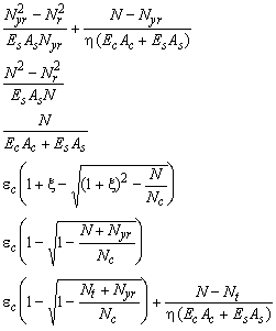
The constitutive relation e[N] of a stringer of reinforced concrete with a constant force is summarised below. Also the derivatives e´ with respect to the stringer force N are presented for computation of the tangent stiffness of the stringer.


![]()

![]()
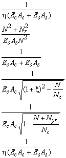

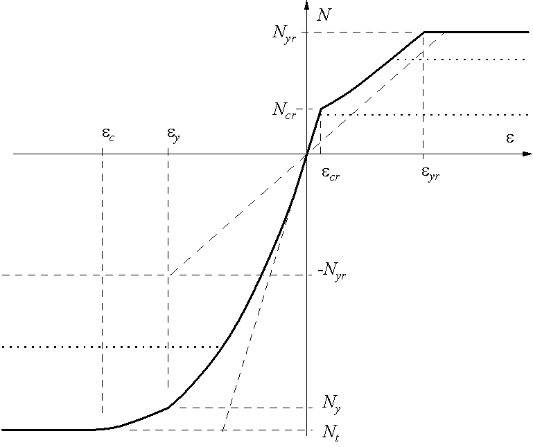
Figure 60: The constitutive relation of a stringer with a constant force. The dotted lines show the reduction of the ultimate strength in order to model design behaviour.
The code for computing the material behaviour in the integration points is printed below. It is part of the routine StringerStrain which computes the average strain e and its derivative de. It is called for the computation of average stresses in the integration points as shown in the next section.
Nyr:=As*fy;
if Ec*Ac=0.0 then writeln(‘Error: Stringer has no Ec or Ac’);
r:=Es*As/(Ec*Ac);
if N>0.0 then
begin { ----------------- tension ---------------------------- }
  Ncr:=fcr*Ac*(1.0+r);
  Nr:=Ncr/sqrt(1.0+r);
  if N>Nyr then
  begin                                             { yielding }
    t1:=Ec*Ac+Es*As; t2:=n*t1;
    if Nyr>Ncr then
      e:=(Nyr*Nyr-Nr*Nr)/(Es*As*Nyr)+(N-Nyr)/t2;
    else
      e:=Nyr/t1+(N-Nyr)/t2;
    de:=1/t2;
  end
  else
  begin
    if N>Ncr then
    begin                                            { cracked }
      t1:=N*N; t2:=Nr*Nr; t3:=Es*As;
      e:=(t1-t2)/(t3*N);
      de:=(t1+t2)/(t3*t1);
    end
    else
    begin                                             { linear }
      t1:=Ec*Ac+Es*As;
      e:=N/t1;
      de:=1/t1;
    end
  end
end
else
begin { ----------------- compression ------------------------ }
  ec:=2.0*fc/Ec;
  Ncd:=fcd*Ac; Nyrd:=fyd*As;
  t1:=1.0+r; t2:=Ncd-Nyrd; t3:=Ncd*t1*t1;
  if t2>t3 then Nt:=t2 else Nt:=t3;
  Nc:=fc*Ac;
  if N>Nt then
  begin                                 { steel does not yield }
    t2:=sqrt(t1*t1-N/Nc);
    e:=ec*(t1-t2);
    de:=1.0/(Ec*Ac*t1);
    if e<-fy/Es then
    begin                                       { steel yields }
      t1:=sqrt(1.0-(N+Nyr)/Nc);
      e:=ec*(1.0-t1)/Nc));
      de:=1.0/(Ec*Ac*t1);
    end
  end
  else
  begin                                             { crushing }
    t2:=sqrt(t1*t1-Nt/Nc);
    e:=ec*(t1-t2);
    if e<-fy/Es then
      e:=ec*(1.0-sqrt(1.0-(Nt+Nyr)/Nc))
    t3:=n*(Ec*Ac+Es*As);
    e:=e+(N-Nt)/t3;
    de:=1/t3;
  end
end
In the previous Section the relation of the load N and the average strain e of a stringer was derived. In this Section the result is used to derive the behaviour of a stringer loaded with a uniform force per unit length at the centreline (see Figure 61).
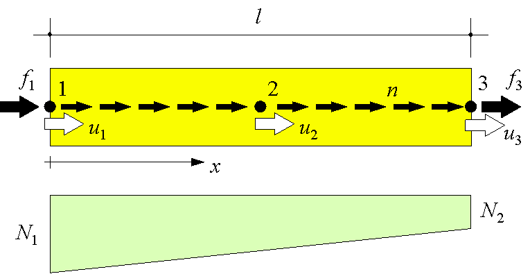
Figure 61: A uniform load n per unit length at the stringer centreline results in a linear distribution of the stringer force N.
This force n, together with the forces f1 and f3 at the begin and at the end of the stringer, give three forces that have to fulfil one equilibrium relation. So, only two independent generalised stresses N1 and N2 are available to describe the stress field. The three stringer forces are accompanied by three discrete displacements u1, u2 and u3 in the direction of the stringer axis. In order to eliminate the rigid body displacement in this direction only two independent generalised stresses e1 and e2 are available. The relations, which derived in this Section are shown in Figure 62.
The stringer has a local reference system with one axis that starts at grip 1 and ends at grip 3. The local stringer displacements and forces are related to the global co-ordinate system with the matrix T. In case of the linear-elastic model only the displacements in the grips at the begin and at the end of the stringer are transformed since the displacement at the midst of the stringer is already in the same direction as the displacement of the edges of the adjacent panels. The advantage of this is that less degrees of freedom are used which speeds up the computation and increases the stability of the model.
In the nonlinear model this is not possible anymore because the panels carry normal stresses. Therefore, the displacements of adjacent panels and stringers midsts are not in the same direction anymore. So, in the nonlinear model also the displacements at the midst of the stringers are transformed to the global co-ordinate system.
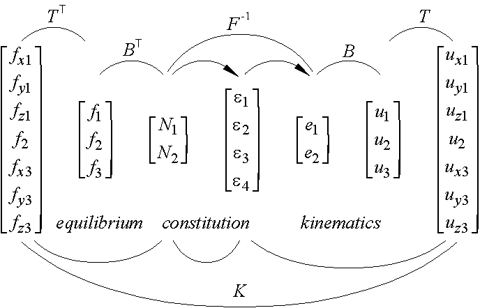
Figure 62: The relations of the stringer quantities
The contribution of the stringer force fi to the nodal forces is

In this a is the angle of the x axis of the global reference system and the stringer axis. The angles b and g are between the stringer axis and the y and the z axis, respectively. The local grip displacement ui can be expressed in the global nodal displacements with
![]()
So, in case of a linear model the rotation matrix T becomes

and in case of a nonlinear model it is 4

In the local reference frame, a stringer has three degrees of freedom u1, u2, and u3 as mentioned before (see Figure 61). 5 In any other direction the stringer has no stiffness. For example the stringer has no resistance to bending both in and out of plane. In this Section the stringer relations are derived using complementary potential energy. Of course, this elegant method yields the same result as a direct method does.
As Figure 62 shows the forces f1 and f3 are present at both stringer ends in the direction of the stringer axis. N is the normal force in the stringer and n is the uniform shear load per unit length along the stringer. In the context of complementary potential energy the displacements u1 and u3 are fixed and f1 and f3 are support reactions. Also the displacement along the whole stringer axis is fixed and the edge force n is the ensuing support reaction.
The total complementary potential energy V of the stringer is

A linear distribution of the stringer force is described by two independent variables N1 and N2.
![]()
Equilibrium shows that the stringer forces are
![]()
Substitution of the latter in the expression of the complementary potential energy gives

The last term in this expression is the shear force along the stringer multiplied with the average stringer displacement u2 which we select to be a degree of freedom.

The force distribution will occur for which the complementary potential energy reaches a minimum. At the minimum the derivatives with respect to N1 and N2 will equal zero. 6


In these equations, the order of differentiation and integration is interchanged. We define now the generalised displacements
![]()
Which are indeed independent on rigid displacements. So,
 (1)
(1)
and
 (2)
(2)
The tangent flexibility matrix F is found by repeating the differentiation’s.


In which
![]()
It can be observed easily that the tangent flexibility matrix F is symmetric regardless of the constitutive behaviour.

Defining the matrix B
![]()
the equilibrium relations and the kinematic relations can be written as
![]()
![]()
in which
 ,
, ![]() ,
, ![]() and
and 
Finally, the stringer tangent stiffness matrix K can be computed with
![]()
Due to the sparse matrices involved it is computationally efficient to derive the stiffness matrix analytically instead of computing the matrix multiplications.
In case the stringer material is linear-elastic with a strain stiffness EA the constitutive relation is
![]()
The flexibility matrix evaluates to
![]()
Substitution in the previous relation for the stiffness matrix yields

The following code adds the contribution of the nonlinear stringer to the internal force vector f and the tangent stiffness matrix S. It uses the routine StringerForces for the computation of the stringer forces and the tangent flexibility matrix as derived in the subsequent Sections.
a:=Str[StrNr].Cosa;
b:=Str[StrNr].Cosb;
c:=Str[StrNr].Cosc;

k:=3*Str[StrNr].NodeNr[1]; v[1]:=k-2; v[2]:=k-1; v[3]:=k;
k:=3*Str[StrNr].NodeNr[2]; v[4]:=k-2; v[5]:=k-1; v[6]:=k;
k:=3*Str[StrNr].NodeNr[3]; v[7]:=k-2; v[8]:=k-1; v[9]:=k;

u1:=u[v[1]]*a+u[v[2]]*b+u[v[3]]*c;
u2:=u[v[4]]*a+u[v[5]]*b+u[v[6]]*c;
u3:=u[v[7]]*a+u[v[8]]*b+u[v[9]]*c;

e1:=u2-u1;
e2:=u3-u2;

StringerForces(StrNr, e1, e2, N1, N2, e11, e12, e22);

f[v[1]]:=f[v[1]]-N1*a;
f[v[2]]:=f[v[2]]-N1*b;
f[v[3]]:=f[v[3]]-N1*c;
f[v[4]]:=f[v[4]]+(N1-N2)*a;
f[v[5]]:=f[v[5]]+(N1-N2)*b;
f[v[6]]:=f[v[6]]+(N1-N2)*c;
f[v[7]]:=f[v[7]]+N2*a;
f[v[8]]:=f[v[8]]+N2*b;
f[v[9]]:=f[v[9]]+N2*c;

d:=e11*e22-e12*e12;
if d=0.0 then writeln(‘Error: Stringer matrix is singular.‘);
t1:= e22/d;  t2:=-e12/d;
t3:=-e12/d;  t4:= e11/d;

aa:=a*a; ab:=a*b; ac:=a*c;
ba:=b*a; bb:=b*b; bc:=b*c;
ca:=c*a; cb:=c*b; cc:=c*c;

t5:=t2-t1;
t6:=t1-t3;
t8:=t2-t4;
t9:=t4-t3;
t7:=t5-t9;

K[1,1]:= aa*t1;  K[1,2]:= ab*t1;  K[1,3]:= ac*t1;
K[2,1]:= ba*t1;  K[2,2]:= bb*t1;  K[2,3]:= bc*t1;
K[3,1]:= ca*t1;  K[3,2]:= cb*t1;  K[3,3]:= cc*t1;
K[4,1]:=-aa*t6;  K[4,2]:=-ab*t6;  K[4,3]:=-ac*t6;
K[5,1]:=-ba*t6;  K[5,2]:=-bb*t6;  K[5,3]:=-bc*t6;
K[6,1]:=-ca*t6;  K[6,2]:=-cb*t6;  K[6,3]:=-cc*t6;
K[7,1]:=-aa*t3;  K[7,2]:=-ab*t3;  K[7,3]:=-ac*t3;
K[8,1]:=-ba*t3;  K[8,2]:=-bb*t3;  K[8,3]:=-bc*t3;
K[9,1]:=-ca*t3;  K[9,2]:=-cb*t3;  K[9,3]:=-cc*t3;

K[1,4]:= aa*t5;  K[1,5]:= ab*t5;  K[1,6]:= ac*t5;
K[2,4]:= ba*t5;  K[2,5]:= bb*t5;  K[2,6]:= bc*t5;
K[3,4]:= ca*t5;  K[3,5]:= cb*t5;  K[3,6]:= cc*t5;
K[4,4]:=-aa*t7;  K[4,5]:=-ab*t7;  K[4,6]:=-ac*t7;
K[5,4]:=-ba*t7;  K[5,5]:=-bb*t7;  K[5,6]:=-bc*t7;
K[6,4]:=-ca*t7;  K[6,5]:=-cb*t7;  K[6,6]:=-cc*t7;
K[7,4]:=-aa*t9;  K[7,5]:=-ab*t9;  K[7,6]:=-ac*t9;
K[8,4]:=-ba*t9;  K[8,5]:=-bb*t9;  K[8,6]:=-bc*t9;
K[9,4]:=-ca*t9;  K[9,5]:=-cb*t9;  K[9,6]:=-cc*t9;

K[1,7]:=-aa*t2;  K[1,8]:=-ab*t2;  K[1,9]:=-ac*t2;
K[2,7]:=-ba*t2;  K[2,8]:=-bb*t2;  K[2,9]:=-bc*t2;
K[3,7]:=-ca*t2;  K[3,8]:=-cb*t2;  K[3,9]:=-cc*t2;
K[4,7]:= aa*t8;  K[4,8]:= ab*t8;  K[4,9]:= ac*t8;
K[5,7]:= ba*t8;  K[5,8]:= bb*t8;  K[5,9]:= bc*t8;
K[6,7]:= ca*t8;  K[6,8]:= cb*t8;  K[6,9]:= cc*t8;
K[7,7]:= aa*t4;  K[7,8]:= ab*t4;  K[7,9]:= ac*t4;
K[8,7]:= ba*t4;  K[8,8]:= bb*t4;  K[8,9]:= bc*t4;
K[9,7]:= ca*t4;  K[9,8]:= cb*t4;  K[9,9]:= cc*t4;

for k:=1 to 9 do
begin
  i:=v[k];
  for l:=1 to 9 do
  begin
    j:=v[l];
    S[i,j]:=S[i,j]+K[k,l];
  end
end
As derived in the next Section the tangent flexibility matrix and the generalised strains can be computed from the stringer geometry and the grip forces. This is programmed in the routine StringerGenStrains (see page 102). However, the displacement method used for the computation of the whole stringer-panel model requires grip forces to be computed from grip displacements. So, the other way around, the stringer forces need to be computed from the generalised strains.
The following code is part of a routine called StringerForces which has as input the generalised strains e1new and e2new and has as output the new stringer forces N1, N2 and the flexibility matrix e11, e22, e12. The algorithm is purely incremental since Newton Raphson iterations appeared not to converge sometimes. The accuracy of the result can be improved by increasing the number of steps NrStrainSteps. More than 5 steps will be rarely necessary. In the last four lines of the code the internal forces are corrected in case they exceed the ultimate loads.
N1:=Str[StrNr].N1;
N2:=Str[StrNr].N2;
StringerGenStrains(StrNr, N1, N2, e1, e2, e11, e12, e22);

de1:=(e1new-e1)/NrStrainSteps;
de2:=(e2new-e2)/NrStrainSteps;

for i:=1 to NrStrainSteps do
begin
  d:=e11*e22-e12*e12;
  if d=0.0 then
    writeln(‘Error: Stringer stiffness matrix is singular.’);
  N1:=N1+( e22*de1-e12*de2)/d;
  N2:=N2+(-e12*de1+e11*de2)/d;
  StringerGenStrains(StrNr, N1, N2, e1, e2, e11, e12, e22);
end

Str[StrNr].N1:=N1;
Str[StrNr].N2:=N2;

if N1<Nt  then N1:=Nt;
if N1>Nyr then N1:=Nyr;
if N2<Nt  then N2:=Nt;
if N2>Nyr then N2:=Nyr;
The above expressions for e1, e2 and the tangent matrix can be approximated for computation with a cubic polynomial g trough four equidistant integration points (see Figure 63). The area under g is

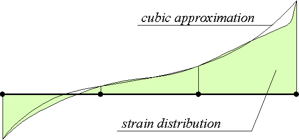
Figure 63: Numerical integration with 4 integration points
With this the generalised strains can be approximated.
![]()
![]()
As a check, the linear relation e = N / EA is substituted in the previous formulas. The result evaluates to
![]()
![]()
which is identical to analytical result (see page 98).
For the computations the tangent matrix is required too.
![]()
![]()

Similar relations for e1 and e2 can be derived heuristically: Suppose that u2 is not the average but the displacement of the middle of the stringer. Then e1 is the elongation of the left-hand half of the stringer and e2 the elongation of the right-hand half. So, e1 is the integration of the strain e over the left-hand half of the stringer and e2 the integration over the right-hand half. Assuming a piece wise linear strain distribution as an approximation we find (see Figure 64).
![]()
![]()
The following code for computing the flexibility matrix and the generalised strains e1 and e2 from stringer forces N1 and N2 is part of a routine called StringerGenStrain. It calls the routine StringerStrain (see page 91). The last 6 lines of this code will be explained in the subsequent Section on ductility.
StringerStrain(StrNr,       N1,          a1, b1 );
StringerStrain(StrNr, 0.333*N1+0.667*N2, a2, b2 );
StringerStrain(StrNr, 0.667*N1+0.333*N2, a3, b3 );
StringerStrain(StrNr,                N2, a4, b4 );

t1:=Str[StrNr].Length*0.0417;

e1:=t1*(3.0*a1+6.0*a2+3.0*a3       );
e2:=t1*(       3.0*a2+6.0*a3+3.0*a4);

e11:=t1*(3.0*b1+4.0*b2+    b3       );
e12:=t1*(       2.0*b2+2.0*b3       );
e22:=t1*(           b2+4.0*b3+3.0*b4);

e1p:=0.0;
if a1>eyr then e1p:=t1*3.0*(a1-eyr);
if a1<ec  then e1p:=t1*3.0*(a1-ec);
e2p:=0.0;
if a4>eyr then e2p:=t1*3.0*(a4-eyr);
if a4<ec  then e2p:=t1*3.0*(a4-ec);

Figure 64: The generalised strain e2 can be derived from the grey area of the right-hand half under the strain curve.
It is a wide spread misconception that the ductility of reinforced concrete can be described with only ultimate average strains applied to either tension or compression. If this would be implemented the model behaviour would strongly depend on the number and position of the integration points in the stringer which is equivalent to mesh dependence in finite element programs. The reason is that not only the average strain but also the dimensions of the region over which failure takes place are important for the ultimate deformation. In finite element theory several methods are being developed to solve this problem including higher-order continua and relating the fracture energy to the element size. For the stringer-panel model a pragmatic approach was adopted to relate the ductility to the plastic deformation as is formulated in this Section.
When either of the stringer forces N1 or N2 reaches its maximum the reinforcement will yield. Due to the linear distribution of the stringer force this will take place at one of the stringer ends. If the stringer forces do not change, any increase of the generalised strains e1 and e2 from the onset of yielding will be due to plastic deformation.
The total generalised strain e1 is derived in the previous Section.
![]()
Just before yielding the strain in the left-hand stringer end is the yield strain eyr.
![]()
If this strain e1e is subtracted from the total strain e1 the plastic part of the generalised strain e1p is obtained at the left-hand stringer end (see Figure 65).
![]()
The same derivation can be applied to the right-hand stringer end and in case of compression. The results are
![]()
![]()
![]()
The generalised strains are defined before as
![]()
We assume the deformation to be elastic. If the stringer is extended at the right-hand end with a plastic displacement D3 the generalised strain becomes
![]()
Similarly, if the stringer is extended at the left-hand end with a plastic displacement D1, then e1 is
![]()
Note that the displacement u2 is interpreted as the displacement in the middle of the stringer which is more accurate than the average displacement in this situation. When the elastic relations are subtracted from the ones including plastic elongations the plastic generalised strains are found.
![]()
So, the plastic deformations of the stringer ends equal the plastic generalised strains.
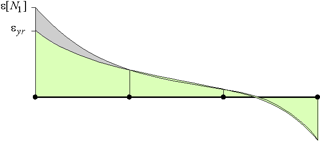
Figure 65: The plastic contribution to the generalised strain e1 is represented by the dark grey area in the figure.
When two connected stringers make an angel more than 135° it is assumed that the plastic deformation of the connected stringer ends localises at the node. This will be referred to as continuing stringers. Suppose that the stringer numbers are i and j and that they are both connected at their first grip. If the stringers continue the total plastic deformation in the connection is
![]()
In case the stringer directions are both towards or from the node (see Figure 66) the condition for continuity is
![]()
In this a, b and g are the angles of the stringer axis 1 or 2 with the x, y and z axis, respectively. If one stringer direction is toward the node and the other from the node the condition becomes
![]()
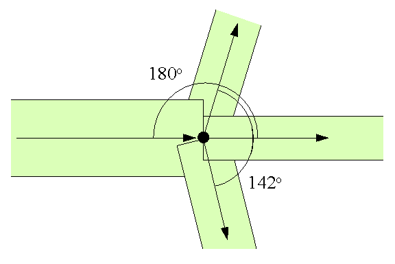
Figure 66: Stringers continue if the difference in direction is more than 135°. In this case we assume that deformation of the connected ends will localise in the node.
When the stringer is cracked the tension-stiffening reduces with increasing stringer force as formulated on page 85. However, experiments show that when yielding starts and progresses the tension-stiffening increases which reduces the ductility substantially. The author was not able to find an explicit expression for this behaviour in literature. Careful study of experimental data [Langer 1987] shows that the average strain em around one crack in a reinforced concrete stringer subjected to tension can be approximated with (see Figure 67)
![]()
In this esu is the ultimate reinforcement strain as found in a simple tensile test. It varies from 0.02 to 0.10 depending on the steel type. In the SPanCAD program a value of 0.03 is used as default which can be changed by the user. Since the elastic deformation is very small compared to the plastic deformation it can be neglected when determining the maximum plastic elongation. Therefore,
![]()
The crack spacing ls is calculated with the Model Code [ENV 1992, art. 7.4.3.1.1.]
![]()
In this, d is the average bar diameter and r the reinforcement ratio.
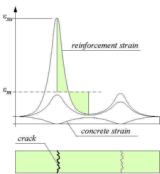
Figure 67: The distribution of the local strain in reinforced concrete shows the strong increase of the strain in a crack just prior to failure.
In the latter it was assumed that the steel will yield in only one crack of the stringer. This is usually the case if the reinforcement does not harden since usually the stringer forces at both sides will differ. Nevertheless, situations can occur in which the stringer force is constant over the length. For example a four point bending test in which the bottom and top cord have a constant force in the middle part of the beam. A second example are strut-and-tie models to which stringers can also be applied. In these models, ties always have a constant force over the length.
If the stringer force is constant, the steel will not only yield at a stringer end but in all cracks, provided that more than the minimum reinforcement is present. When the ultimate steel stress is reached the reinforcement starts to neck which will take place in only one crack. The rest of the bars will unload elastically. So, in case of a constant stringer force the ultimate plastic strain is
![]()
in which est is the reinforcement strain at the maximum stress and the elastic deformation is neglected again (see Figure 68). The stringer length l should be larger than the crack spacing ls. Since data on est usually is not available the relation is approximated as
![]()
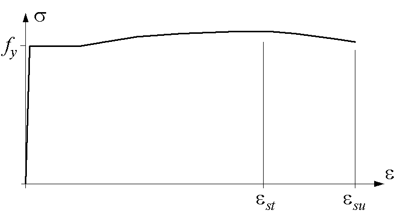
Figure 68: The stress-strain curve of reinforcing steel. In the softening part of the curve from est necking occurs.
Hardening of the reinforcement after yielding, has a considerable influence on the ultimate load of a structure. This is not only due to the larger strength of hardening reinforcement but also because reinforced concrete with hardening reinforcement is much more ductile. The latter is easily explained because the deformation of hardening reinforcement does not localise in one crack. Instead, the reinforcement will yield in several cracks. This makes that the tensioned reinforced concrete can deform much more locally, which allows more global redistributions and a larger structural strength. Hardening of the reinforcement is not included in the current ductility formulation and should be addressed in future research.
The ultimate strain for compression varies considerably from -0.0015 to -0.0195 for concrete with little reinforcement (see Figure 69). Moreover, the ultimate strain is substantially increased in case of confinement. The model code advises a conservative ultimate strain of ecu = -0.0035 which was adopted for the stringers in compression [CEB-Bulletin 1993, art. 2.1.4.4.1. and art. 6.2.2.2.]. The strain et at top load depends on the amount of compression reinforcement. When the top load is reached the damage localises in one failure zone. 7
The dimensions of the failure region in compression are rarely included in a presentation of test data. Based on some experience and after discussion with experimental researchers the length of the compression failure is chosen to be equal to the height or the width of the stringer cross-section which ever is the smallest (see Figure 70). So, the ultimate plastic deformation in compression is the largest of
![]()
and
![]()

Figure 69: The ultimate strains at the edge of concrete beams varies substantially. [Adapted from Langer1987, p. 50].

Figure 70: The length of the failure region in a stringer is the smallest of the width or the height of the cross-section.
In the SPanCAD program it is checked for every stringer if the plastic elongation D is larger than the ultimate plastic elongation D u. If this is the case the model is considered to have collapsed and the simulation is stopped. Situations can occur in which breaking of one stringer does not lead to total collapse. For example in case of low ductility reinforcement in a highly redundant structure. However, we are not able yet to keep the computational algorithm stable when a grip force disappears abruptly. For this, gradually softening constitutive relations need to be implemented and further improvements need to be made to the arch length method. So, in case that a simulation stops in an ascending load-displacement curve, at least one stringer is broken but perhaps the structure could carry more.
The stringer formulation was already derived in 1993. The element served satisfactory in many computations and therefore in this text the early derivation is reproduced with a few improvements. More information can be found in [Hoogenboom 1993, pp. 16-25].
Yielding can include hardening. If no hardening is present a small tangent stiffness is used to increase the robustness of the computation of the stringer forces. However, this has no consequence to the stringer forces because they are cut off at the yield strength if hardening is not present (see page 101).
In order to increase the robustness of the computation of the stringer forces a small tangent stiffness was implemented. However, this has no consequence for the stringer forces because they are cut off when its extreme value is exceeded.
For clarity the zero elements of the matrices are represented with dots ( . ).
More degrees of freedom could be included in the stringer formulation. For example end rotations to include bending behaviour or bond slip to model pull out of reinforcement. This would definitely improve the accuracy of the model, however, it would also increase the computation time and the results would be difficult to display and interpret in the graphical user-interface.
In this Section square brackets [ ] denote a matrix or contain the argument of the function whilst round brackets ( ) contain a factor.
The value of the ultimate strain can be easily changed in the graphical user-interface SPanCAD but only experts will be able to handle this option well.