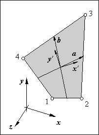
Figure 90: The panel geometry is transformed from space to a two dimensional reference frame.
A panel can have any shape and position in a three dimensional space. Moreover, it does not have to be perfectly plane since a little curvature should not influence its behaviour significantly. In this appendix relations are derived to transform the panel vertices from the global reference frame to a two dimensional panel reference frame in order to be able to apply the relations of the Appendices 2 and 3.
The local reference frame serves four purposes.
|
First, it makes the panel behaviour independent of its orientation in space: In the discrete element method an element represents a physical part of a structure. Therefore it is not acceptable that the element properties change when it is rotated in space. This is opposite to the finite element method in which often shape functions are conveniently defined in the directions of the global reference frame. Properties of such elements will change with rotations but in the finite element method this is considered to be a negligible error of the discretising mesh.
Second, it defines the directions of the distributed reinforcement: In a stringer-panel model the distributed reinforcement in the panels is applied in the directions of the local reference frame. It would have been easy to include multiple layers of reinforcement with their angles. However, we do not want to bother a designer with questions about angles since the program can determine what obviously are the directions of the reinforcement.
Third, it eliminates small curvatures of the panel surface: In the graphical user-interface of SPanCAD panels can be copied, resized, moved and so forth. Due to computer inaccuracies of these manipulations, panels may not remain perfectly plane. So, in order to apply the two dimensional derivations of Appendix 2 and 3 this curvature has to be eliminated. As shown in the next section, this is accomplished by projecting the panel vertices on the plane spanned by the local reference frame. 1
Fourth, as is shown in the Appendices 2 and 3, a well chosen reference frame simplifies the panel relations considerably.
The panel reference frame has two perpendicular axis that are as good as possible parallel with its edges. Figure 90 shows that the plane of the panel is spanned by the vectors a and b that connect the midsts of opposite edges.
The vectors x' and y' of the local panel reference frame are a linear combination of these vectors.

Moreover, x' and y' are perpendicular. So,
Substitution of the latter three equations gives a quadratic equation in l
that can be written as
 |
with
Thus, two solutions are found
of which the one with the smallest absolute value is correct.
Computationally this is a pathological formulation since often the absolute value of t will be very large. So, it has to be limited in order to prevent t2 from producing an overflow of the computer real number capacity as shown in Section A-4.4.
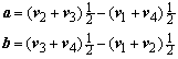
In Figure 91, three panel geometries are drawn with their local reference frames as derived in this appendix. Though the reference frames are uniquely defined, the panel relations derived in previous appendices are not accurate for the extreme geometries of the lower two panels.
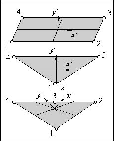
The panel vertices can be transformed from three dimensional space to the panel reference frame by using the transformation matrix T .
v Is the vector to a vertex while v' is the transformed vector in the local reference frame. The vector pointing to the origin of the panel reference frame is denoted t. In general the transformation matrix is
In this, x is a vector along the x axis of the global reference frame and x' is a vector along the x axis of the panel reference frame. Since the vectors x' and y' of the panel reference frame both have a unit length the transformation matrix simplifies to
The third component of the transformed vector is zero since the vertices are projected to the plane of the panel reference frame.
In order to show that the relations can be implemented efficiently, the PASCAL code is given to transform the global vertices to the panel reference system. It consists of 74 additions or subtractions, 57 multiplications, 7 divisions and 3 square roots. The code uses 32 real number memory locations.
{ --------------- panel vectors a and b -------------------- }
ax:=x[2]+x[3]-x[1]-x[4];
ay:=y[2]+y[3]-y[1]-y[4];
az:=z[2]+z[3]-z[1]-z[4];
bx:=x[3]+x[4]-x[1]-x[2];
by:=y[3]+y[4]-y[1]-y[2];
bz:=z[3]+z[4]-z[1]-z[2];

{ --------------- factor lambda l -------------------------- }
d:=2.0*(ax*bx+ay*by+az*bz);
e:=ax*ax+ay*ay+az*az+bx*bx+by*by+bz*bz;
if abs(d)>e*0.0000001 then
   begin
   t:=e/d;
   if abs(t)>=1 then
      begin
      if t>=1 then
         l:=-t+sqrt(t*t-1);
      else
         l:=-t-sqrt(t*t-1);
      end
   else
      writeln('Panel reference system cannot be established.');
   end
else
   l:=0.0;

{ --------------- x and y vector of reference frame -------- }
xx:=ax+l*bx;
xy:=ay+l*by;
xz:=az+l*bz;
yx:=bx+l*ax;
yy:=by+l*ay;
yz:=bz+l*az;
lx:=sqrt(xx*xx+xy*xy+xz*xz);
if lx>0.0 then
   begin
   xx:=xx/lx;
   xy:=xy/lx;
   xz:=xz/lx;
   end
else
   writeln('Error: Panel x axis has no length.');
ly:=sqrt(yx*yx+yy*yy+yz*yz);
if ly>0.0 then
   begin
   yx:=yx/ly;
   yy:=yy/ly;
   yz:=yz/ly;
   end
else
   writeln('Error: Panel y axis has no length.');

{ --------------- vertices in local co-ordinates ----------- }
xm:=(x[1]+x[2]+x[3]+x[4])*0.25;
ym:=(y[1]+y[2]+y[3]+y[4])*0.25;
zm:=(z[1]+z[2]+z[3]+z[4])*0.25;
for i=1 to 4 do
   begin
   tx:=x[i]-xm;
   ty:=y[i]-ym;
   tz:=z[i]-zm;
   xl[i]:=tx*xx+ty*xy+tz*xz;
   yl[i]:=tx*yx+ty*yy+tz*yz;
   end
{ --------------- end -------------------------------------- }
Despite a possible curvature of the panel, the positions of the panel grips in the global co-ordinate frame coincide with those of the local panel co-ordinate frame. So, when the panel forces are transformed to the global co-ordinate system the panel is still in perfect equilibrium. The positions of the panel vertices, however, do differ in the global and the local co-ordinate system in case of a curved panel.